Interfaces and couplings
Sixty-six interfaces exist between the twelve subsystems, and every pair has at least one. Thirty-seven of the 66 are high criticality, 25 medium and 4 low. That saturation is itself the finding: at this level of integration there is no isolated subsystem change, and the order in which a team freezes its numbers matters more than the order in which it designs its parts.
Key takeaways
- The arm and perception each touch nine high-criticality interfaces, the most of the twelve. A team that plans the arm last and the cameras as the design proceeds has chosen the two worst places to defer decisions.
- A change to the arm’s length, mass or stow pose re-opens nine interfaces; a wheel-diameter change re-opens seven and is irreversible once the wheels and gear ratios are made.
- Delivery is a mission, not an interface hub. It has one high interface, the arm’s 5 kg grasp, because it reuses everyone else’s interfaces and its risk sits in the mission sequence.
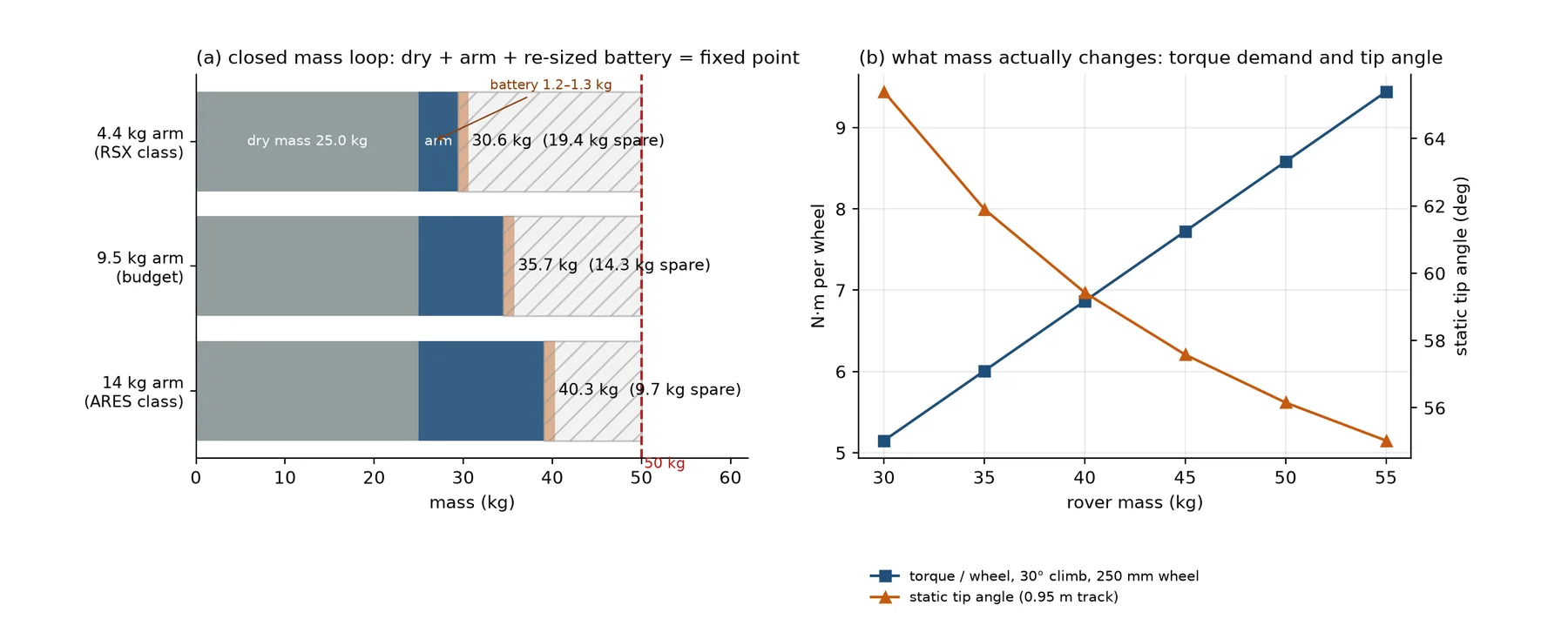
- The arm’s mass silently chooses the drivetrain. A 4.4, 9.5 or 14 kg arm puts the rover at 30.6, 35.7 or 40.3 kg, and the 9.0 N·m actuator class runs out at 40.6 kg, so one more bracket can force a 2.7 kg actuator step.
Twelve nodes, five kinds of interface
Each subsystem is a node that trades in a small set of numbers. Every interface is one of five types, because the five fail in different ways and are owned by different engineers.
| Code | Type | What crosses it | Typical failure when it is unmanaged |
|---|---|---|---|
| M | mechanical | Mounting patterns, envelopes, mass, centre of gravity, stiffness, retention | Interference found at assembly; a stow that does not fit at weigh-in |
| E | electrical | Rails, currents, fusing, grounds, inrush, the scope of the E-stop | Brownout, a welded contactor, an E-stop that does not cut everything |
| D | data | Protocols, rates, schemas, timestamps, calibration files | Un-synchronised odometry; a camera that resets when a motor stalls |
| T | thermal | Conduction paths, dissipation, ambient, solar gain, derating | The sealed-box oven that works in the lab and fails at the site |
| t | timing | Clocks, sequences, setup and teardown, mission windows | A correct rover that runs out of mission clock |
Timing is an interface type rather than a management afterthought because the competition scores it. The astrobiology clock is 20–30 min, the autonomy-to-servicing transition can be as short as 10 min, and setup is 15 min including the weigh-in and all communications S-URC27-RULES S-URC27-QA §1.a.ii–§1.e.i EQ4. A design that is two minutes too slow loses the same points as a design that does not work.
The 12 × 12 matrix
Each cell is the interface as seen from the subsystem in that row. The letters give the interface type, in descending order of dominance, followed by its criticality: H high, M medium, L low. The upper triangle is the authoritative entry and the lower triangle repeats it so the table can be read in either direction. The diagonal is a subsystem’s own business and is marked n/a.
| Row, column | 01 | 02 | 03 | 04 | 05 | 06 | 07 | 08 | 09 | 10 | 11 | 12 |
|---|---|---|---|---|---|---|---|---|---|---|---|---|
| 01 MOB | n/a | M+E·H | M+t·M | M+D·M | M+E+D·H | E+T·H | M+D·H | D+t·H | D+t·M | M·H | M+T·H | M+t·M |
| 02 ARM | M+E·H | n/a | M+D·H | M·H | D+t·M | E·H | M+D·H | D+t·H | D+t·M | M·H | T+M·H | M·H |
| 03 SCI | M+t·M | M+D·H | n/a | t+M·M | D·M | E·H | D·M | D+t·M | D+t·H | M·H | T·H | t·L |
| 04 DEL | M+D·M | M·H | t+M·M | n/a | D+t·M | E·M | D·M | D·L | t·M | M+t·M | M·L | t·L |
| 05 COM | M+E+D·H | D+t·M | D·M | D+t·M | n/a | E·H | D·H | D+t·H | D+t·H | D·H | M+T·H | D·M |
| 06 PWR | E+T·H | E·H | E·H | E·M | E·H | n/a | E·H | E+D·M | E·M | M+E·M | T·H | E·M |
| 07 CMP | M+D·H | M+D·H | D·M | D·M | D·H | E·H | n/a | D+t·H | D·H | M·H | T+M·H | D·H |
| 08 SFT | D+t·H | D+t·H | D+t·M | D·L | D+t·H | E+D·M | D+t·H | n/a | D+t·H | D+t·M | T·M | D+t·H |
| 09 OPS | D+t·M | D+t·M | D+t·H | t·M | D+t·H | E·M | D·H | D+t·H | n/a | t·H | t+M·M | t+D·H |
| 10 SYS | M·H | M·H | M·H | M+t·M | D·H | M+E·M | M·H | D+t·M | t·H | n/a | M+t·H | D+t·M |
| 11 ENV | M+T·H | T+M·H | T·H | M·L | M+T·H | T·H | T+M·H | T·M | t+M·M | M+t·H | n/a | T·M |
| 12 AST | M+t·M | M·H | t·L | t·L | D·M | E·M | D·H | D+t·H | t+D·H | D+t·M | T·M | n/a |
Five readings follow from the matrix. The two most coupled subsystems are the arm and perception at nine high interfaces each, one mechanical and one data-dominated. Seven subsystems sit at six or seven, so there is no clean partition into core and periphery. Delivery has a single high interface, which is evidence that its difficulty is in the mission sequence rather than in a novel coupling. The astronaut node is data and timing dominated, with the arm as its only high mechanical interface. Every power interface carries an electrical term, and the only one without it is the thermal link to the environment node, because the E-stop rule makes one subsystem carry a system function S-URC27-RULES §2.a.v.
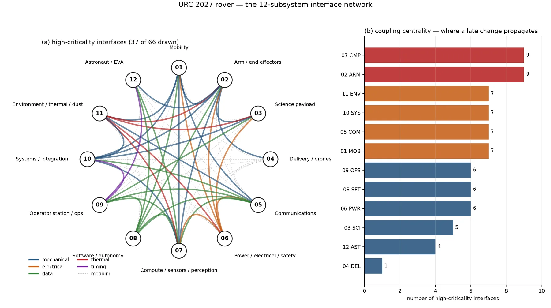
| Rank | Subsystem | High interfaces | What it means for the schedule |
|---|---|---|---|
| 1–2 | Arm (02), compute and perception (07) | 9 | Freeze their mounting, power and data contracts first; both are long-lead |
| 3–6 | Mobility (01), comms (05), systems (10), environment (11) | 7 | These host other subsystems’ mass, masts and heat, so a change invalidates several interface documents at once |
| 7–9 | Power (06), software (08), operations (09) | 6 | Broad but shallow: each interface is a number or a schema that can change independently |
| 10 | Science (03) | 5 | Contained as a bay, which is exactly why its internal integration of fluids, heat and time is where it fails |
| 11 | Astronaut interaction (12) | 4 | Mostly data; the suit is allowed to be a separate system |
| 12 | Delivery (04) | 1 | A mission, not an interface hub |
Eight interfaces with a number that forces a decision
| Interface | What crosses the boundary | Risk if it is ignored |
|---|---|---|
| Arm to mobility | Shoulder reaction 176 N·m peak; an arm from 4.4 to 14 kg raises the centre of gravity from 0.222 to 0.282 m and cuts the static tip angle from 64.9° to 59.3° on a 0.95 m track | An arm mounted on a suspension link moves relative to the wheels; the deck must be a structural node |
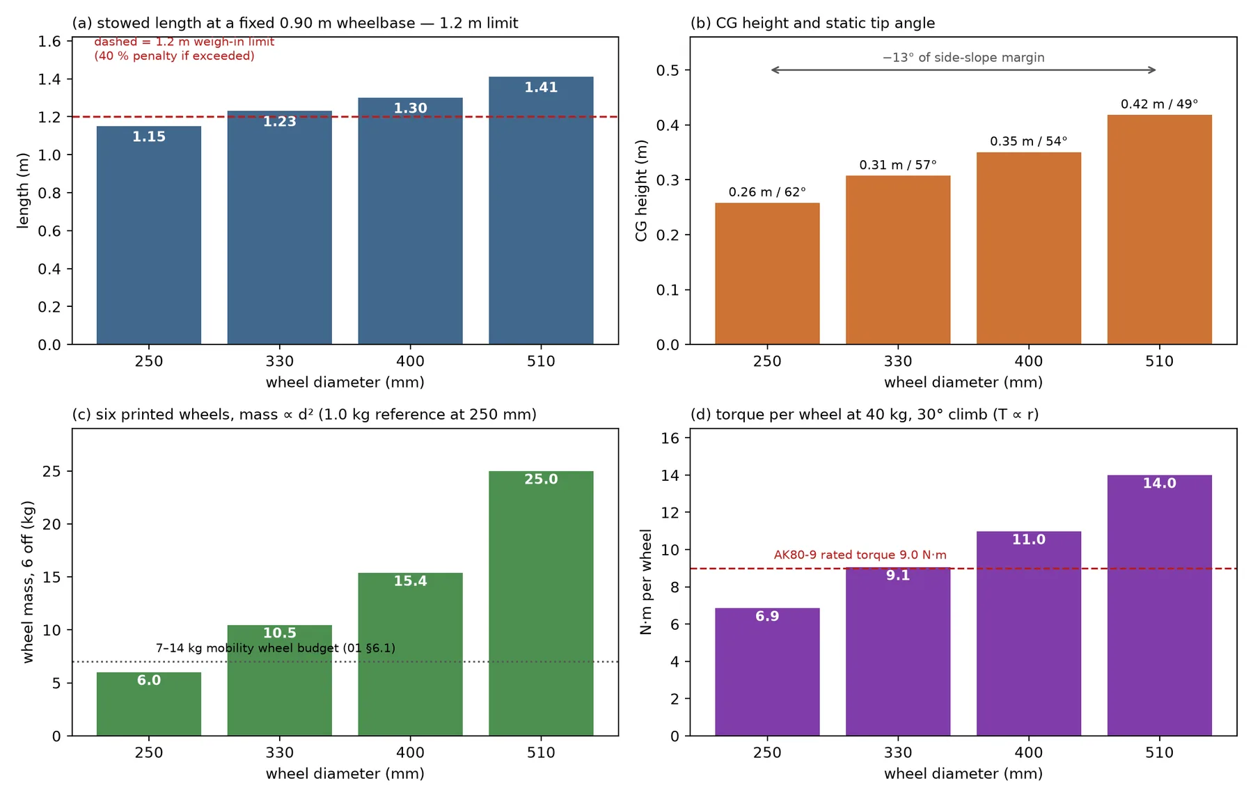
| Wheel diameter to stow | A 250 mm wheel on a 0.90 m wheelbase gives 1.15 m; 330 mm gives 1.23 m and fails; 510 mm gives 1.41 m | Decides whether a fold mechanism exists at all, with a 40 % penalty if the cube fails |
| Camera mast to structure | A 30 mm carbon tube, 0.8 m, 0.5 kg tip, has its first mode at 19 Hz; a 20 mm tube gives 9 Hz, inside the 2–15 Hz terrain band | A flexible post destroys stereo calibration and visual odometry |
| Mast loads to mobility | A 65 km/h gust gives 155 Pa; 23 N·m for a 0.15 m² antenna at 1 m, 78 N·m for a 0.5 m² dish at 3 m | A mast load path through the science box cracks the box |
| Power to environment | 40 W in a 0.52 m² box: 195 W of solar absorbed by a black skin gives 77 °C internal, white 55 °C, shade 50 °C, a filtered fan 42 °C | The sealed-box oven is the classic works-in-the-lab failure |
| Power to arm | 28 A peak per joint; about 1.1 kW for two joints moving, and hold current unless brakes are fitted | A stalled arm is the usual cause of a battery-management trip, at 561 W per joint continuously |
| Perception to software | ArUco id, range and bearing at 10–30 Hz, range error 0.3 % of distance at 60 pixels or more; command events carrying confidence and method | A six-degree-of-freedom pose from a 30-pixel tag is worse than the bearing, and the method field is what scores |
| Systems to operations | 15 min of setup including weigh-in and all communications; a six-minute mast leaves nine minutes for everything else | Every subsystem’s setup ritual competes for the same clock |
The full register is 41 rows across the five types: ten mechanical and stow, seven electrical, ten data, six thermal and eight timing. Every high cell in the matrix is represented by at least one row. The table below searches and filters by interface type.
The three chains that carry the most consequence
| Chain | First step | Second step | Third step | Fourth step |
|---|---|---|---|---|
| 1. Arm mass sets the drivetrain | Arm 4.4, 9.5 or 14 kg | Rover 30.6, 35.7 or 40.3 kg | Cliff at 40.6 kg against a 9.0 N·m actuator | Next actuator class at +2.7 kg for six, 43.0 kg fixed point |
| 2. Wheel diameter sets the box and the centre of gravity | 250 mm: 1.15 m, 61.5° | 330 mm: 1.23 m, fails the cube | 510 mm: 1.41 m, 48.6°, 25 kg of printed wheels | Torque at a 30° climb grows from 6.9 to 14.0 N·m |
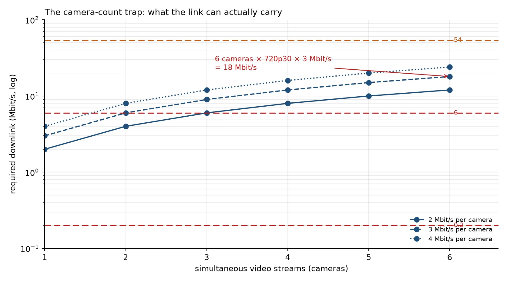
| 3. Camera count sets the link and the clock | 6 × 3 Mbit/s = 18 Mbit/s | 2.4 GHz: 6 Mbit/s at 2.62 km; 900 MHz: 0.2 Mbit/s at 1 km | 0.5 m/s teleoperation = 33 min for 1 km | A 30-minute stage runs out of clock |
Chain 1: arm mass to drivetrain to points. The mass loop is stable and converges in two iterations with a loop gain of 0.0137 kg of battery per kilogram of rover, so forgetting to re-size the pack after adding the arm is wrong by 0.16 kg. The danger is two cliffs. At 250 mm wheels, a 45° loose slope and 45 kg requires 9.97 N·m per wheel, and an AK80-9 is rated 9.0 N·m S-CUBEMARS-AK80-9. Inverting the formula gives 40.6 kg. The 14 kg ARES-class arm lands at 40.3 kg, 0.3 kg below the cliff, so one more bracket forces a 0.94 kg actuator class at +0.45 kg per wheel or +2.7 kg for six, re-opening the budget at 43.0 kg with 7.0 kg of headroom. The arm is not 4.5 kg lighter than the alternative; it is 4.5 kg plus the actuator class it preserves. No published team process owns the margin-to-cliff number.
Chain 2: wheel diameter is a four-way, irreversible coupling. It changes climbing, centre-of-gravity height, stow length and torque in conflicting directions. From 250 to 510 mm costs 12.9° of static tip angle, against 5.6° for an arm change from 4.4 to 14 kg. Six printed wheels grow from 6.0 to 25.0 kg, torque at 40 kg on a 30° slope grows from 6.9 to 14.0 N·m, and overall length grows from 1.15 to 1.41 m. Only top speed improves, from 5.1 to 10.4 m/s at rated motor speed, against a design target of 0.5–2.0 m/s.
The field evidence agrees. WVU ran 20-inch wheels in 2024, 24-inch in 2025 and back to 20-inch with no folding mechanism in 2026, giving up 2 inches of climbing radius to fit the cube without a fold S-WVU-SAR2025 S-WVU-SAR2026. Missouri S&T moved to a suspension that no longer needs to fold to fit the 1.2 m box S-MST-SITE-ATHENA. Two of the strongest teams independently concluded that geometry beats mechanisms. The defensible point for a first build is 250–300 mm with a 0.85–0.95 m wheelbase and no fold, which leaves 40–50 mm per side for suspension links and tolerance.
Chain 3: camera count is a link-budget decision that converts into stage time. Six cameras at 720p30 and 3 Mbit/s each demand 18 Mbit/s. The 900 MHz link carries 200 kbps at 1 km, which is 1.1 % of the demand; 2.4 GHz carries 6 Mbit/s at 2.62 km and 54 Mbit/s at 0.42 km; 5.8 GHz with the radio at the mast carries 6 Mbit/s at 21.4 km. Dropping from the fastest modulation to 6 Mbit/s buys about 9 times the range. At 1 km and 0.5 m/s the Delivery traverse takes 33 minutes, which does not fit a 30-minute stage, and WVU’s 2026 tri-band system was tested to only 750 m line of sight and 164 m obstructed S-WVU-SAR2026. The camera count must be frozen against the link: three or four streams, adaptive bitrate, and a separate stills path.
Two shorter chains. Arm reach against stow and typing is not a horizontal problem: a 1.05 m arm folds to 0.55 m and fits with 0.65 m to spare, but the parked vertical budget is only 0.12–0.15 m, and the fold joint that solves it adds backlash at the worst lever. At 4.4–5.2 mrad, the shoulder’s 1.05 m lever gives 4.6–5.5 mm of lost motion at the tip, four joints sum to 9.7–11.4 mm, and the typing target is ±3 mm against a 5.0 mm geometric limit. The resolution is a wrist camera and visual servoing, which turns the shoulder term into 1.8 mm at a 0.35 m lever, not a low-backlash reducer at every joint.
Mast height against stability and the cube is the other. The stowed stack already uses 0.84 m of the 1.2 m envelope before the mast, so a 2.0 m mast leaves 0.06 m and a 2.5 m mast fails. The same 30 mm tube has its first mode at 19 Hz at 0.8 m, 4.8 Hz at 2.0 m and 2.6 Hz at 3.0 m, inside the 2–15 Hz terrain band. A 20 mm tube is at 9 Hz at 0.8 m. The resolution is two masts: a tall guyed radio mast and a short stiff camera post, the only fold a first team should keep.
Conflicts that no subsystem can settle
Fourteen decisions cannot be made inside one subsystem, because each has an owner on both sides. The table gives the two sides and the review by which the answer is needed.
| ID | Conflict | The two sides, with numbers | Decide by |
|---|---|---|---|
| CF-01 | Arm mass against drivetrain margin | A 9.5 kg arm gives 35.7 kg, 4.9 kg below the 40.6 kg cliff; a 14 kg arm gives 40.3 kg, 0.3 kg below | Preliminary design |
| CF-02 | Reach against stow against typing precision | 1.5 m reach, 0.12–0.15 m parked height, ±3 mm typing | Preliminary design, then SAR |
| CF-03 | Wheel diameter against cube, centre of gravity and torque | 250 mm fits and is light; 510 mm climbs but costs 12.9° of tip angle and 19 kg of wheel mass | Preliminary design, irreversible |
| CF-04 | Mast height against camera stability and the cube | 3 m helps the link; 3 m is 2.6 Hz and 1.29 m stowed | Preliminary design |
| CF-05 | Camera count against link and operator load | Six streams demand 18 Mbit/s against 6 Mbit/s at range, and an operator watches three to six | Preliminary design |
| CF-06 | Compute power against thermal and volume | A 25 W computer in a 77 °C sealed box against a separate battery bay | Preliminary design and SAR |
| CF-07 | Bioassay against arm stiffness and the 25-minute clock | Wet chemistry, a 10.5-minute acquisition block, a mandatory assay | December 2026, before the SAR video |
| CF-08 | Modularity against swap time and staffing | 20 kg of second configuration against a 10-minute window and six seats in the control station | Preliminary design |
| CF-09 | E-stop scope against comms and logging | One button must cease all power draw, which also kills the link | Preliminary design, verified at SAR |
| CF-10 | Drone accounting | 5 kg including a dummy is excluded from the rover’s limits; the treatment in the 70 kg total is not stated | Preliminary design, by a question to the Director |
| CF-11 | Whether the servicing cache is the astrobiology cache | A reusable cache against two designs; the rulebook leaves it open | December 2026 |
| CF-12 | Astronaut link topology | A rover-relayed path dies beyond about 20–30 m, which is the stay-test geometry, against a second receiver at the control station | Preliminary design |
| CF-13 | Base-station survey against the setup clock | A 30–60 minute survey against 15 minutes of total setup | SAR |
| CF-14 | 900 MHz sub-band agility against a multi-link network | 8 MHz in one of three sub-bands for all links, including drone and suit | 2027-04-30, the licence date |
The freeze order follows the penalty, not the subsystem number
The interfaces whose consequence is a rule penalty are frozen first; the rest are a re-test. A worse but frozen choice beats a better but late one, which is also the judges’ own advice on design stability S-URC-ADVICE.
| Interface | Freeze by preliminary design | Freeze by SAR | Consequence of a late change |
|---|---|---|---|
| Mass allocation and the 50 and 70 kg plan | Allocation, 15 % growth, 1.5 kg reserve | Weighed values replace estimates | 5 % of points per kilogram per event, and a re-allocation re-opens every mounting interface |
| Stow concept: fold or geometry | Concept and vertical stack, with the 0.06 m margin identified | CAD envelope check into a timber mock box | 40 % penalty at every weigh-in; a new fold is a new failure mode with no test time |
| Wheel diameter and wheelbase | Fixed, because tooling and gear ratio depend on it | Wheel mass and bearing choice | Seven interfaces re-open, and the 250 to 330 mm step adds 2.2 N·m per wheel at 40 kg |
| Arm link lengths, mount and end effector | Reach class and mount location | Link lengths, end-effector change, wrist camera | Chassis hardpoint, stow pose, inverse kinematics and typing strategy all change together |
| Bus voltage and connector families | The 12, 24 or 48 V decision | Connector part numbers | The E-stop rating, fusing, every harness and every board input |
| E-stop topology | Single contactor loop with the status driver independent of compute | Test evidence in the SAR video | A pass or fail rule breach, with no partial credit |
| Comms bands, antennas and licence documents | Bands, antennas, base station | Range and throughput at realistic geometry | The licence date is 2027-04-30, and a band change invalidates the link budget |
| Camera count and video pipeline | Count, codec, bitrate ladder | Operator display and adaptive-bitrate behaviour | The station layout, link budget, thermal load and power all move |
| Science assay pair and fluid bay | Assay pair chosen in December | Fluid path, heater, waste containment, cache interface | A post-SAR change is unscored in the review and unproven in the field |
| Autonomy schema: state, telemetry | Schema version one | Version two with logging and replay proven | Every operator screen and every log depends on it |
Open problems
- No team publishes a mass, power or centre-of-gravity budget, so every mass-distribution number in the chains is an engineering estimate with its stated basis.
- The weigh-in duration is not published, which is one reason not to build a mission plan around a fast re-weigh.
- Teleoperation ground speed and glass-to-glass latency are not measured by any team; both are inputs to the camera-chain arithmetic and both need a field test.
- Whether a drone counts toward the 70 kg total, and whether a spare drone battery falls under the one E-stop rule, is not stated in the rules and changes a design S-URC27-RULES §2.b.vii.
- Whether the Equipment Servicing cache is the team’s own astrobiology cache is open, and it changes both the cache and the end-effector design.
Further reading
- Mass and power carries the mass and pack numbers these chains consume.
- How rovers fail shows which of these interfaces actually breaks on the field.
- Coupling and trades works the fourteen conflicts as trade studies.
- Systems engineering owns the allocation and the review gates.
Sources for this page
- S-URC27-RULESUniversity Rover Challenge 2027 – Requirements and GuidelinesOriginal Archived copy
- S-URC27-QAURC2027 Questions & Answers (updated through 2026-10-11)Original Archived copy
- S-CUBEMARS-AK80-9CubeMars AK80-9 V3.0 robotic actuator product page (specs, $479.90)Original
- S-WVU-SAR2025Team Mountaineers System Acceptance Review 2025 (rover "Daedalus"): 2.4 GHz 90° sector + 3 m rover mast, 70 cm HAM packet radios, 433.25 MHz amateur-TV analog video, 750 m LOSOriginal
- S-WVU-SAR2026Team Mountaineers System Acceptance Review 2026 (rover "Deimos"): tri-modal 2.4 GHz + 5.8 GHz + 70 cm, gimbal camera on antenna mast, 750 m LOS / 164 m NLOS high-noise test, antenna + radio budget linesOriginal
- S-MST-SITE-ATHENAAthena (2026) rover page, compact suspension, 3D-printed wheels, hub motors, STM32/CAN controllers, simulator arm, LiDAROriginal
- S-URC-ADVICEURC Advice (judges' systems-engineering lessons)Original Archived copy