Power, electrical architecture and safety
The electrical architecture has to satisfy a pass/fail safety rule before it meets any performance target. One red push button must stop the rover and remove all battery power, and that requirement tightened in 2026, so a design copied from an earlier season may no longer comply. This chapter fixes the numbers that size the pack, ranks the kill-chain options, and sets out the enclosure thermal problem that decides whether the electronics survive a June afternoon in the Utah desert.
Key takeaways
- Average power sizes the battery; peak power sizes the protection. The 2027 mission set needs 273 to 289 Wh of nameplate capacity, and a 400 to 500 Wh pack is the sensible buy. The same rover draws about 145 A at 3.7 kW for a few seconds, which is what the fuse, contactor, connector and wire have to survive.
- The E-stop is the highest-severity item in the subsystem. The 2026 and 2027 wording requires one button to switch off all power from any and all batteries. A drive-only kill fails the rule.
- The kill removes compute power too. Filesystems and logs have to be designed for an unannounced power cut, not a shutdown sequence.
- A sealed black box reaches about 88 °C internally at 38 °C ambient. A sunshade and a filtered fan bring it to roughly 42 °C, and no pack survives a season at the first number.
What the subsystem must do
The rules state the safety requirement without ambiguity, and this page quotes it because every word drives a part choice:
“All rovers shall have a red push button emergency stop that is readily visible and accessible on the exterior of the rover. It must be a push button, not a knob or rotating switch. This push button shall immediately stop the rover’s movement and cease all power draw from any and all batteries in the event of an emergency such as a battery fire. All systems on the rover must have the power switched off by this single E-stop.” S-URC27-RULES §2.a.v
Six constraints follow. The button is red and push-actuated. It is exterior and findable. It stops movement and removes battery power, which a wheel disable does not do. No second switch or software menu may stand between the button and a dead rover. Its action is immediate, so a shutdown sequence does not qualify. And it must work when the pack’s own electronics are the thing that failed, which rules out any path through a microcontroller.
The surrounding requirements set the operating envelope. Mobile deployables such as a mini-rover need their own E-stop, while a fuse is enough for anything that cannot move S-URC27-RULES §2.a.vi. No tether to the C2 station may carry power S-URC27-RULES §2.a.i. No air-breathing power source is allowed, but cooling fans are explicitly permitted and need not be custom S-URC27-RULES S-URC27-QA §2.a.iv RQ12. The mission clocks run from 20 minutes for Astrobiology to 60 minutes for Delivery, with no recharge in between S-URC27-RULES S-URC27-RULES §1.b.ii §1.c.i. Set-up is 15 minutes S-URC27-RULES §1.a.ii. Site power is 120 V at 60 Hz S-URC27-RULES §3.d.i. June ambient is 37.8 °C with dust and light rain S-URC27-RULES §3.d.iii. And any intervention to swap a pack or reset a tripped protection device costs 20 % of that mission’s points S-URC27-RULES §3.e.
The numbers that size the design
| Quantity | Value | Basis |
|---|---|---|
| Average mission power | ≈249 W for a 50 kg rover on a 35-minute mission | Ten-row load table, by inference |
| Mission energy | ≈146 Wh for that 35-minute mission | Same load table |
| Nameplate for one mission | 273 Wh for the 60-minute Delivery; 289 Wh for Autonomy followed by Equipment Servicing | Mission energy, 25 % margin, 0.662 usable fraction |
| Recommended pack | 400–500 Wh nameplate at 8S, 2.4–2.9 kg with BMS and enclosure | Covers the back-to-back case with 38–73 % headroom |
| Peak current | ≈145 A, ≈3.7 kW at the sagged 25.6 V bus | Climb, arm hold and radio together, for a few seconds |
| Pack sag at peak | 4.6 V on an 8S4P pack, 15.6 % of nominal | 32 mΩ pack resistance S-VENDOR-MOLICEL-P42A-DS |
| Cell energy and mass | 15.5 Wh and 70 g per 21700 cell; 496 Wh and 2.24 kg for 32 cells | Datasheet S-VENDOR-MOLICEL-P42A-DS |
| Precharge energy | 2,000 µF at 33.6 V is 1.13 J; about 646 A without a resistor | Computed loop resistance; 100 Ω precharge gives 0.34 A and a 0.2 s time constant |
| Sealed-box temperature | about 88 °C internal at 38 °C ambient | Solar gain on a 0.5 × 0.5 × 0.25 m box |
| Cooling requirement | about 10.6 CFM for 60 W and a 10 K rise | Enclosure cooling rule of thumb, verified against a fan curve |
Two numbers govern the whole design. The first is the average, which sets the pack. The second is the peak, which sets everything downstream of the pack: fuse, contactor, connector, wire gauge and the battery management system’s trip curve. A team that sizes protection for the average melts, trips or welds on the first loose slope.
Design space, in one table
| Decision | Options | Recommended for a first build |
|---|---|---|
| Chemistry | Li-ion 21700 · LiPo pouch · LiFePO4 | 8S4P Li-ion 21700 at about 496 Wh and 2.3 kg of cells; a bought 8S LiPo if the first mission is under six months away; LiFePO4 only to avoid lithium fire risk, at 2.3× the mass |
| Voltage | 6S · 8S · 12S · 24S | 8S, at 29.6 V nominal and 33.6 V full. A 6S pack forces 1.33× the current through the same harness; 12S only if every converter and contactor is 60 V rated |
| Kill device | DC contactor · MOSFET e-fuse · controller disable · wireless | A hardwired contactor driven by the button, with precharge. A MOSFET is distribution protection, not the primary kill |
| Protection settings | fixed BMS trip · programmable trip with delay | A programmable BMS whose current limit sits above a legitimate two-joint stall |
| Distribution | central board with per-output sensing · fuse block and bought converters | Fused branches with per-output sensing if an electronics subteam exists; otherwise one 24 V bus and three bought converters |
| Thermal | passive · forced air · sunshade | Sunshade, white exterior and filtered forced air |
Average power sizes the battery, peak power sizes the protection
The load table below is a defensible first-order model for a six-wheel skid-steer rover with a six-joint arm, one Jetson-class computer, a 2.4 and 900 MHz radio pair and a small science package. The structure is the deliverable; every number should be replaced with a measurement in the first month of driving.
| Load | Quantity | Rail | Average each | Duty | Average total |
|---|---|---|---|---|---|
| Drive motors and controllers | 6 | 24 V | 20 W | 0.55 | 120 W |
| Arm joints, hold and move | 6 | 24 V | 8 W | 0.5 | 48 W |
| Perception computer | 1 | 12 to 5 V | 20 W | 1.0 | 20 W |
| Auxiliary computer and MCU | 2 | 5 V | 4 W | 1.0 | 8 W |
| Radio and switch | 1 | 12 V | 9 W | 1.0 | 9 W |
| Cameras, GNSS, IMU | 6 | 5 and 12 V | 2 W | 1.0 | 12 W |
| Science package | 1 | isolated 12 V | 15 W | 0.8 | 12 W |
| Status LEDs and lights | 1 | 12 V | 8 W | 0.6 | 5 W |
| Fans | 4 | 12 V | 1.5 W | 1.0 | 6 W |
| Converter losses | Not applicable | Not applicable | 8 % of the loads above | Not applicable | 9 W |
| Total | ≈249 W |
The peak is a different calculation, and it comes from three sources. A 50 kg rover climbing a 25° loose slope at 0.5 m/s needs about 190 W electrical, which is nothing. Wheel slip and obstacle climbing at the controller’s 20 A limit are the real drive case: six motors at 20 A is 120 A at 24 V, about 2.9 kW. One shoulder joint holding 8 kg at 0.9 m needs about 71 N·m at the output, which through a 50:1 reducer and a torque constant of 0.06 N·m/A is about 23 A and 560 W per joint, and two joints together are about 1.1 kW. Climbing while the arm holds a sample while the radio transmits is ≈145 A and 3.7 kW for a few seconds.
That peak has four consequences. It is about 15 times the average draw, so it sets the fuse, contactor, connector and wire while the average sets the pack. On an 8S4P pack it is an 8.6C discharge, inside the pack’s 180 A rating but hot, and far beyond a single 30 A protection device or a 45 A connector. It sags the bus by 4.6 V, so converters need a wide input range and the low-voltage cut-off has to sit below the sagged voltage or the rover dies on the hill by design. And it is usually the arm, not the drivetrain, that causes a trip, because a stalled joint draws that current continuously while a person decides what to do. Missouri S&T’s published protection trips at 80 A for longer than 10 ms and restores after 3 s, which would trip on a legitimate two-joint stall S-MST-2023-POWER.
Two fixes are cheaper than a bigger pack: interlock the firmware so the drive current limit drops while the arm moves, and give the arm brakes so a hold costs no current at all.
The E-stop is a pass/fail clause, not a lost point
The wording has tightened twice, and the history explains why this subsystem needs a procedure rather than a component:
| Season | Requirement text | What changed |
|---|---|---|
| 2023 | a kill switch, readily visible and accessible, that stops movement and ceases power draw | no colour, no actuator, no dimension S-URC23-RULES §3.a.v |
| 2024 | a red push button at least 3 cm across, mounted away from moving parts, plus a strongly encouraged heartbeat monitor | first dimension, first mention of a comms-loss failsafe S-URC24-RULES §3.a.v |
| 2025 | a red push button emergency stop, dimension language dropped | colour retained, detail removed S-URC25-RULES §3.a.v |
| 2026 and 2027 | adds “not a knob or rotating switch”, “any and all batteries”, and all systems off from this single button | the strongest version S-URC27-RULES §2.a.v |
Four ways to remove power exist, ranked here by what a field judge can verify:
| Option | Strength | Weakness |
|---|---|---|
| DC contactor in the battery lead, coil broken by the button | Physical gap a judge can see; fails open; survives a dead BMS | Coil current, mass, and it welds without precharge |
| High-side MOSFET or e-fuse | Microseconds, no wear, can report its own state | No physical gap; a shorted device keeps the rover live |
| Motor-controller disable | Free, already wired | Does not comply: converters, radios and computers keep drawing |
| Wireless kill | Useful as a supplement | Cannot be an exterior button on the rover, and depends on a working link |
The recommended chain is short and entirely hardware. Pack, then a 125 A class-T fuse within 150 mm of the positive terminal, then the normally-open contactor with a precharge bypass across its contacts, then distribution. The latching red mushroom sits in series with the contactor coil through two normally-closed contacts, one of which also feeds a green loop-healthy indicator. A second, smaller enable contact from the protection board sits in series, never in place of the manual kill. Everything the rover owns is downstream of the contactor, which is what makes “all systems switched off” true.
The timing targets are measurable: contacts open within 50 ms of the press, bus voltage reaches zero within 100 ms, and the wheels stop within 0.5 s through brakes or friction.
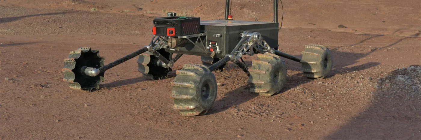
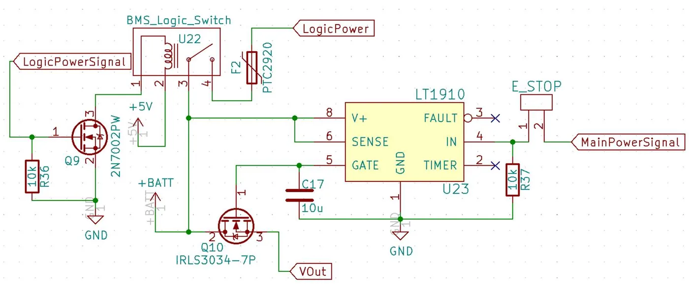
A second design finding matters more than the schematic: mature teams end up with more than one stop path. Missouri S&T built a dedicated arm stop board and a wireless stop board on top of the mandated button, and a separate “rover insurance” board S-MST-2023-POWER. Extra paths are good practice as supplements and a compliance risk if used instead of the button.
Because the kill is literal, the compute dies with it. Logs therefore belong in a continuously flushed file or on a microcontroller, the root filesystem should be read-mostly, and the record of the kill belongs on the C2 side, where the moment telemetry stops is the timestamp. A supercapacitor that flushes a card for 200 ms is not power draw from a battery; a battery-backed uninterruptible supply is, and it does not comply.
The kill is measured, not assumed
- Continuity across the coil circuit, with the button pressed and released.
- Contactor open time on a scope, and every rail below 0.5 V within 200 ms of a press.
- Stopping distance under 0.5 m from 1 m/s.
- The rover stays dead after the button is released, until it is deliberately re-armed.
- Precharge completes before the main contactor closes.
- The whole set repeated with the pack at full charge and the arm moving.
Precharge, and why contactors weld
A motor bus is a capacitor bank, and closing a contactor onto an uncharged bank is a short circuit for milliseconds. For 2,000 µF at 33.6 V the stored energy is 1.13 J, small in absolute terms, but with 52 mΩ of loop resistance the theoretical peak is 646 A, limited in practice to a few hundred amps for a millisecond by the arc and the fuse. A welded contactor is the worst failure in the system: the button works, the coil clicks, and the rover stays live.
A 100 Ω, 25 W wirewound resistor across the contacts fixes it. Peak current becomes 0.34 A, the time constant is 0.2 s, and the bus is at 95 % in 0.6 s, so the main contactor closes with about 1.7 V across it and no arc. The symptom of skipping it is a click and a dead rover; the symptom of a precharge resistor that has gone open is a brownout on every power-up while the main contactor arcs.
Solar gain decides the enclosure
At 1,000 W/m² and an absorptivity of 0.9 for black anodised aluminium, the top face of a 0.5 × 0.5 × 0.25 m enclosure absorbs 225 W. Natural convection and radiation off 0.75 m² give about 4.5 W/K, so the steady-state rise is 50 K, or 88 °C internal at 38 °C ambient. That single number explains why electronics work on the bench and fail at the competition site.
| Measure | Internal temperature, same model | Effort |
|---|---|---|
| Nothing, black sealed box | 88 °C | none |
| Reflective sunshade and white lid | 55 °C | a few grams of sheet and standoffs |
| White or polished exterior | 55 °C | paint |
| Sunshade plus filtered forced air | 42 °C | a fan, two vents, about 1 to 3 W |
| Separate battery compartment | pack cooler than the electronics | volume and a second thermal path |
Two cautions attach to this table. A fan is a silent failure, so monitor tachometer output or temperature and never let forced air be the only thing between the computer and thermal shutdown. And the dust is fine bentonitic clay that will clog a filter in a day of driving, so filter cleaning belongs in the daily routine rather than the pre-competition checklist.
The pack has its own thermal rules. Dwell above 30 °C is elevated temperature for ageing purposes, a cell held at 40 °C and full charge keeps about 65 % of its capacity after a year S-BU-808, and charging is only allowed between 0 and 45 °C S-VENDOR-MOLICEL-P42A-DS. Self-heating at peak is real: 145 A through 32 mΩ is 0.67 kW of heat inside the pack for the duration of the peak, so peaks have to be short or the pack has to be larger.
Interfaces that bite
- Mobility. A 6S pack forces 33 % more current through the same harness for the same power, and a regen-capable controller can over-voltage a full pack on a descent. The drive branch fuse, connector and precharge all follow from the controller’s input capacitance and current limit.
- Arm. Long holds without brakes are a continuous current the pack and the protection must tolerate, and they heat a motor the size of a fist with hundreds of watts. Brakes remove the load, the heat and the trip.
- Communications. The kill removes the radio, so C2 sees silence after a press and must not read it as a fault. The radio also wants a quiet 12 V rail, because sharing with a motor controller costs packets every time the drive moves.
- Compute. Ten to forty watts of compute with peaks near 60 W need a wide-input converter, bulk capacitance and a low-voltage cut-off below the sagged voltage. Motor stall current browning out the cameras is the classic coupling failure.
- Delivery and the drone. A spare drone battery carried on the rover adds mass and cost, and the phrase “any and all batteries” may be read to cover it. A written ruling is worth having before the System Acceptance Review S-URC27-QA RQ14.
- Systems and environment. A 500 Wh pack with BMS and enclosure is about 3 kg and is routinely underestimated in a mass budget. Filter access, pack mounting and drip loops belong in the enclosure drawing, not in the field routine.
Failure modes
| Mechanism | What happens | Prevention |
|---|---|---|
| Protection trip during an arm stall | Sustained 80 to 150 A against a stuck object trips the pack and the rover goes dark mid-task | Trip above legitimate stall current, or current-limit each joint, and add brakes |
| Brownout on a climb | Pack sag drops the bus below converter drop-out and the computer resets | Oversize the pack, use wide-input converters, and set the cut-off below the sag |
| Welded contactor | No precharge, so a later close welds the contacts and the button cannot remove power | Precharge resistor, sequenced closing, a DC-rated contactor and an anti-spark connector |
| Kill loop opened by vibration | An inline connector or crimp fails on rough ground, so the rover dies or the button stops working | One harness, at most one connector in the loop, strain relief, and a continuity check every field day |
| Hot connector | An undersized connector on a 100 A branch opens the circuit or starts a small fire | Size connectors to at least 1.5× the steady current, and check temperature after a full-load test |
| Dust ingress | Fine clay bridges contacts and produces intermittent faults after the first dusty run | Sealed connectors outside the box, drip loops, conformal coating and a cleaned filter |
| Over-discharge during storage | Quiescent drain takes one cell group below its limit and the pack is unusable on the morning of the event | A physical disconnect and a stored-charge schedule |
| Charging failure at the site | A 230 V-only charger on a 120 V supply, or a wrong connector | Dual-voltage charger, a spare, and a bench test on a 120 V circuit |
| Filesystem corruption after a kill | The hard cut damages the filesystem exactly when the log matters | Read-only root, a journalled data partition, or logging to a microcontroller |
The honest limit of that table is that no published URC post-mortem names an electrical failure with a root cause. It is a mechanism-first list, confirmed from the rules and from one detailed team paper rather than from a field incident.
Shortlist for a first build
| Item | Choice | Why |
|---|---|---|
| Pack | 8S4P Li-ion 21700, about 496 Wh, 2.3 kg of cells, bought programmable BMS | Enough energy for the mission set, 180 A of continuous rating for the peak, and no assembly beyond spot-welding |
| Voltage | 8S, 29.6 V nominal, 33.6 V full | The centre of the converter and contactor market; 6S costs 33 % more current |
| Kill | Latching red mushroom into a DC contactor coil, with precharge | Inspectable, fails open, and no firmware in the path |
| Distribution | One 24 V bus, a fuse block, three bought converters for 12 V, 5 V and isolated 12 V | A custom board pays off only if an electronics subteam can freeze it three months out |
| Connectors | XT90-S at the pack, Powerpole for 12 V field power, M12 or Deutsch DT for exterior sensors | One family per voltage, and the correct crimper owned for each |
| Charging | 120 V-native 600 W charger and two packs, charged at 1C between missions | A second pack removes the recharge from the critical path |
| Thermal | Reflective sunshade, white lid, filtered forced air, pack in its own compartment | The cheapest 46 K of the whole design |
Open problems
- What is the real peak current? Published team numbers are averages. A logging shunt and three full mock missions answer it, and every protection setting depends on the answer.
- Do the protection thresholds clear a legitimate peak? Inject a controlled 150 A pulse and confirm no trip, then a 200 A pulse and confirm a trip.
- How hot does the pack run in the real enclosure? The solar-gain model is one-dimensional. Thermocouples on the pack, the computer heatsink and the enclosure air on a 38 °C day replace it with data.
- Must a carried spare drone battery be killed by the single button? The rule says any and all batteries, and a stowed pack is not connected to anything. A written ruling before the review settles it.
- Does the contactor or the MOSFET survive dust and vibration better? Both designs exist in the record and no comparative reliability study has been published. A vibration and dust test with contact-resistance measurement before and after is the honest comparison.
- Does a dust filter survive a day of driving? Measure airflow drop across a filter in a dust chamber or on a dusty field day.
Further reading
- Missouri S&T is the only team in the record with a detailed published electrical paper, covering the pack, the protection logic and a 19-output distribution board.
- Mobility sets the drive current limit and the regen behaviour that this subsystem has to absorb.
- Communications and networking carries the other half of the E-stop consequence: the radio dies with the rover.
- Mass and power places the pack in the 50 kg budget and works the pack-sizing arithmetic in full.
- Interfaces and couplings follows the power, arm and thermal couplings with numbers.
Sources for this page
- S-URC27-RULESUniversity Rover Challenge 2027 – Requirements and GuidelinesOriginal Archived copy
- S-URC27-QAURC2027 Questions & Answers (updated through 2026-10-11)Original Archived copy
- S-VENDOR-MOLICEL-P42A-DSMolicel INR-21700-P42A product data sheetOriginal
- S-MST-2023-POWERRemote Power System Monitoring and Management of a Teleoperated Mars Rover (ITC 2023)Original
- S-URC23-RULESUniversity Rover Challenge 2023 – Requirements and Guidelines (Drive file University Rover Challenge Rules 2023.pdf)Original
- S-URC24-RULESUniversity Rover Challenge 2024 – Requirements and Guidelines (Drive file University Rover Challenge Rules 2024.pdf)Original
- S-URC25-RULESUniversity Rover Challenge 2025 – Requirements and Guidelines (Drive file University Rover Challenge Rules 2025.pdf)Original
- S-BU-808BU-808: How to Prolong Lithium-based BatteriesOriginal