Mobility
Mobility is the subsystem every mission depends on. It carries the rover and its payload across up to a kilometre of soft sand, gravel, boulders and loose slopes, stops within a metre of an AR target, and does all of it inside a 1.2 m cube and 50 kg at every weigh-in. The engineering surprise is that torque is rarely the binding constraint. Traction, packaging and the clock are.
Key takeaways
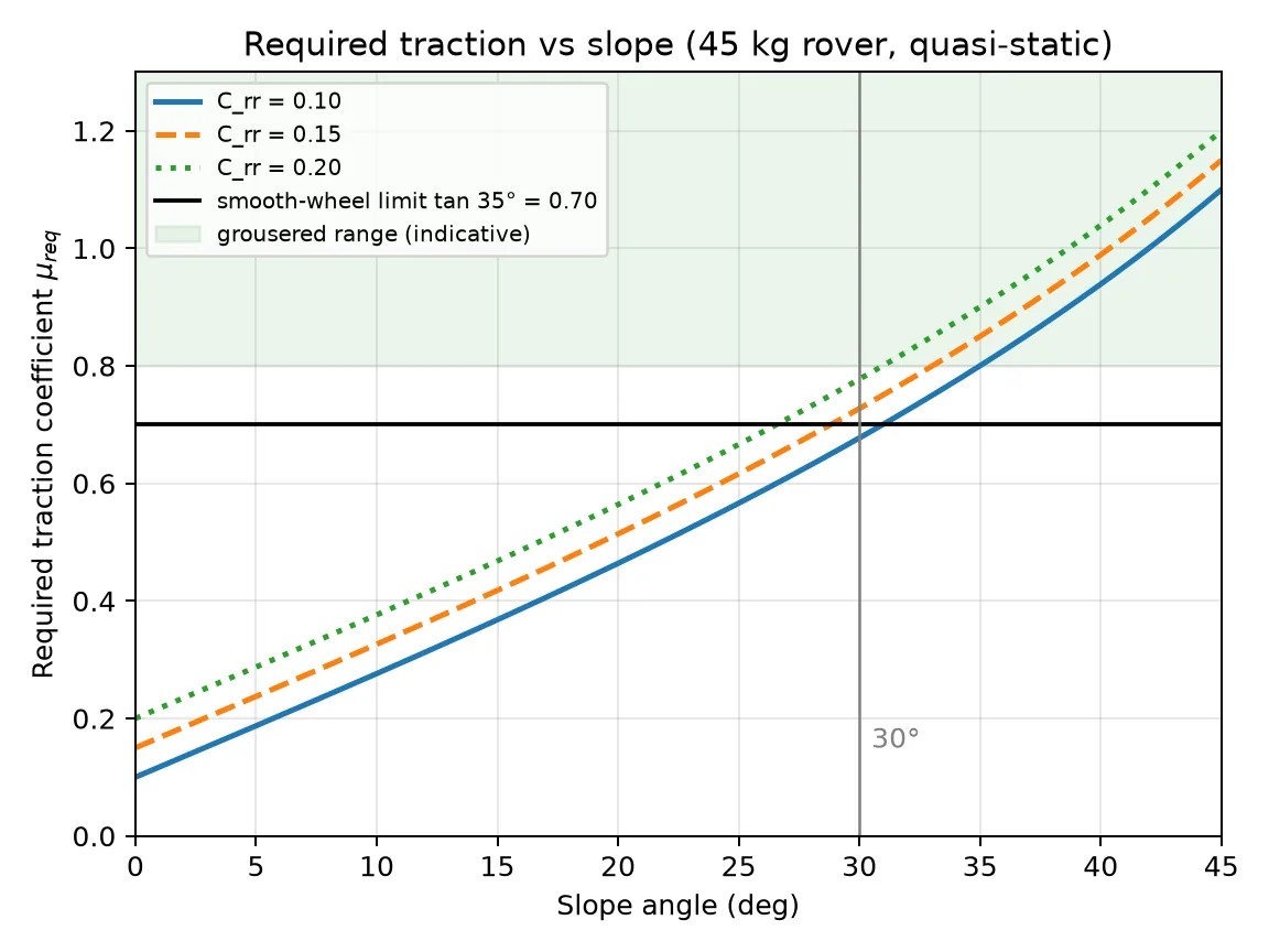
- The 30° climb needs 7.72 N·m per wheel and about 371 W electrical, but it also needs a traction coefficient of 0.727, just above the 0.70 limit of a smooth wheel on cohesionless soil. Grousers and ground pressure decide the climb, not motor size.
- A skid-steer spin turn demands 7.6 N·m per wheel, about as much as the climb, and dissipates roughly 1 kJ. Three-point turns preserve both tread and energy.
- At 250 mm wheels, a 0.9 m wheelbase and a 1.0 m track, the rover is already 1.15 m long and 1.20 m wide before the arm, mast or antenna. The cube is a packaging requirement, not a packing problem.
- Speed is a mission requirement because the clock is fixed. The practical target is 1.0-1.5 m/s on flat gravel and 0.4-0.6 m/s on a 25-30° slope.
What the subsystem must do
The 2027 rules set the mobility envelope in five places. The rover must traverse "soft sandy areas, gravel, rough stony areas, rock and boulder fields, vertical drops and steep loosely consolidated slopes" up to 1 km from the start gate S-URC27-RULES §1.c.ii. It must find a navigable route up a hill where "not all approach directions will be navigable" S-URC27-RULES §1.e.xv. It must stop within 1 m of an AR target S-URC27-RULES §1.e.xvii. It must fit inside 1.2 m on every axis and stay at or below 50 kg in each deployed configuration S-URC27-RULES §2.a.ii. And the E-stop must stop movement and remove battery power, which puts a brake or a self-locking ratio in the drivetrain rather than relying on a zero command S-URC27-RULES §2.a.v.
The rules do not publish a step height or a slope limit for the course. URC declined to give a number when asked S-URC27-QA D1. The design therefore has to choose its own obstacle set and measure against it, rather than design to a published worst case.
The numbers that size the design
The design-speed, climb-torque, skid-scrub, spin-energy and fabrication rows are engineering estimates from the stated parameters. The course range and traction rows rest on the rules and the cited soil mechanics. The packaging and mass rows are budget arithmetic.
| Quantity | Value | Basis |
|---|---|---|
| Course range | up to 1 km from C2; total path may exceed 1 km | Delivery and Autonomy S-URC27-QA RQ13 |
| Design speed | 1.0-1.5 m/s on flat gravel; 0.4-0.6 m/s on 25-30° | Estimate: a 2 km Delivery round trip is 33 min at 1.0 m/s, 67 min at 0.5 m/s |
| 30° climb torque | 7.72 N·m per wheel at the gearbox output; about 371 W total | Estimate from 45 kg, 250 mm wheel, efficiency 0.75, rolling resistance 0.15 |
| Traction at 30° | required coefficient 0.727 against a smooth-wheel limit near 0.70 | tan 35° = 0.70 for cohesionless soil S-UMD-TERRAMECHANICS |
| Skid-spin scrub | 164 N·m yaw moment; 7.6 N·m per wheel | Estimate from 0.9 m track, 0.85 m wheelbase, friction 0.6 |
| Spin energy | about 1.0 kJ per 360° spin | Estimate; equal to climbing about 2.3 m |
| Packaging at 250 mm wheels | length about 1.15 m, width about 1.20 m before arm or mast | 0.9 m wheelbase, 1.0 m track, 80 mm tyre, 60 mm hub overhang |
| Mobility mass | 14-29 kg, or 28-58 % of the 50 kg limit | Frame 5-11 kg; wheels and drive 7-14 kg; controllers 2-4 kg |
| Fabrication effort | 250-400 person-hours for a six-wheel rover | Estimate; 150-250 hours for a four-wheel rocker |
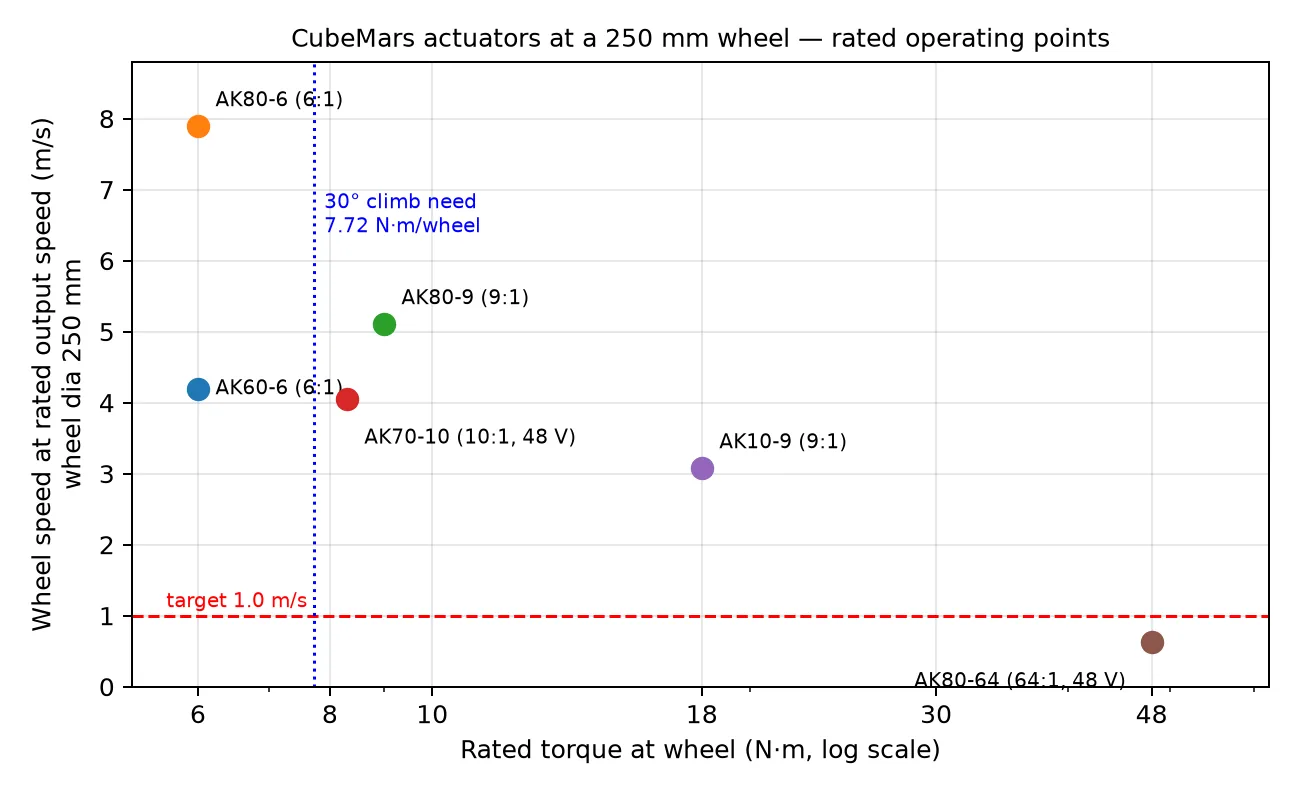
The inversion that matters: the AK80-9 (9:1) on a 250 mm wheel already gives 5.1 m/s at rated speed S-CUBEMARS-AK80-9. Speed is not what the motor lacks. Torque margin and traction are.
Design space, in one table
| Decision | Options | Recommended for a first build |
|---|---|---|
| Wheel count and layout | 4 · 6 · wheel-legs | 6 for redundancy and boulder bridging; 4 when mass and the cube bind, as on Monash and UIU in 2026 |
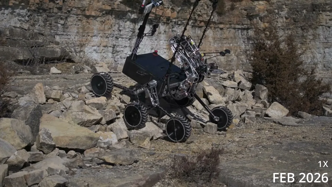
| Suspension | 6-wheel rocker-bogie · 4-wheel rocker · double-lambda · articulated body · independent double wishbone · rigid | 6-wheel rocker-bogie with a differential bar: the largest top-team evidence base and no control law |
| Steering | skid · pivot · swerve | Skid steer: zero steering hardware; pivot or swerve only when fine positioning is the bottleneck |
| Wheel | printed TPU · moulded polyurethane · composite · pneumatic | 250-300 mm printed TPU with 10-15 mm V-chevron grousers and an exchangeable tread |
| Drive | integrated BLDC · BLDC with planetary or cycloidal reduction · hub motor · brushed | 48 V integrated actuators if machining is weak; in-house cycloidal or planetary if it is strong |
| Frame | laser-cut 6061 · welded torsion box · T-slot · carbon fibre | Laser-cut 6061 sheet with bolted or waterjet plate nodes; carbon fibre only with composites experience |
| Folding | fixed compact · folding | Fixed if it fits, as on Missouri S&T 2026; folding adds joints and failure modes, as on BYU and WVU |
Traction and scrub, not torque, size the drivetrain
The worked 45 kg, six-wheel, 250 mm example is the calculation a first-time team should reproduce before buying motors. A 30° loose slope needs 7.72 N·m per wheel and about 371 W electrical, but the required traction coefficient is 0.727, just above the 0.70 smooth-wheel limit of a cohesionless soil with a 35° friction angle S-UMD-TERRAMECHANICS. The motor has torque to spare and the wheels still spin. That is why grousers, a wider contact patch and lower ground pressure matter, and why a larger motor does not fix a loose 30° slope. At 45° the requirement is 1.15, which traction alone cannot deliver. The 2027 answer is route choice, not a gearbox.
Skid steering is the second surprise. A spin turn about the centre produces a 164 N·m yaw moment and demands 7.6 N·m per wheel, more than the 30° climb, and dissipates about 1.0 kJ, the energy of climbing 2.3 m. Skid steer is still right for a first build because the hardware is simple and the wear is gradual. Operators should three-point turn rather than spin, and the tread should have a few millimetres to lose.
The 1.2 m box and the speed arithmetic
At 250 mm wheels, a 0.9 m wheelbase, a 1.0 m track and 80 mm tyres, the rover is already 1.15 m long and 1.20 m wide before the arm, mast or antenna. That is why Missouri S&T shrank its suspension until folding was unnecessary, and why Monash packages at about 1.2 × 1.1 × 0.8 m excluding the mast. BYU and WVU fold. The box allows any orientation but not disassembly S-URC27-RULES §2.a.ii, and a diagonal does not rescue a bounding box that exceeds 1.2 m on an axis.
Speed is a mission requirement because the clock is fixed. Delivery is 30-60 minutes over a 1 km course. Astrobiology is 20-30 minutes within 0.5 km, and two sites are easily 1 km of driving. At 0.5 m/s the 2 km Delivery drive alone is 67 minutes, longer than the mission. The practical target is 1.0-1.5 m/s on flat gravel and 0.4-0.6 m/s on a 25-30° slope, not as fast as possible. Monash quotes 3.6 m/s with 32 N·m continuous at the wheel, and Michigan designs for 30° S-MONASH-2026-SAR S-UMICH-2026-SAR.
Interfaces that bite
Mobility is coupled to almost every other subsystem, and four couplings decide the architecture:
- Arm mass and reach against the wheel diameter. A longer arm needs a stiffer deck; a larger wheel raises the deck and changes the arm's working height. The arm mount and the suspension cannot be designed independently.
- Mast height against the cube. The mast sets the radio horizon and the camera height, and it is the item most likely to break the 1.2 m envelope when stowed.
- Wheel diameter against torque and packaging. A larger wheel raises ground clearance and speed but increases the wheelbase, the packaging length and the motor torque demand.
- Battery mass against the mass budget. The pack is the largest single mass that can move without changing the structure, and it sits low, which helps the tip angle.
The 2027 rules also require the rover to stop within 1 m of an AR target. That is a mobility accuracy requirement at the end of a drive, not only a perception requirement.
Failure modes
The failure record is consistent across teams. Suspension joints and mounts fail under shock, printed treads wear through or delaminate, and a single motor or controller loss turns a six-wheel rover into a five-wheel rover with a dragging corner. Wheels that are too stiff transmit shock into the frame; wheels that are too soft roll off the bead or tear at the hub. The cheapest mitigations are a mechanical fuse in the wheel mount, a tread that can be replaced in the field, and a drivetrain that can isolate one corner.
The 2027 environment adds two more: dust that enters sealed bearings through the shaft, and transport shock into a crate that is also the weigh-in box. Both are testable before the season starts.
Shortlist for a first build
| Item | Choice | Why |
|---|---|---|
| Layout | Six wheels, rocker-bogie, differential bar | Redundancy and boulder bridging with no control law |
| Steering | Skid | No steering hardware, no extra actuators, simple failure modes |
| Wheel | 250-300 mm printed TPU, 10-15 mm V-chevron grousers, exchangeable tread | Traction on loose soil; replaceable wear item |
| Drive | 48 V integrated BLDC, 9:1 class, rated torque at least 9 N·m at the wheel | The 30° climb needs 7.72 N·m; 9 N·m leaves a small margin |
| Frame | Laser-cut 6061 sheet, bolted nodes | Predictable stiffness, repairable, no weld distortion |
| Suspension travel | 60-80 mm at the wheel | Enough for rocks without a complex linkage |
| Mass target | 16-20 kg for the mobility system | Leaves room for arm, science, power and compute inside 45 kg |
Open problems
- What is the real step height? The rules do not publish one. A measured obstacle set from the 2026 course video and a local rock pile is the only defensible basis.
- What is the soil strength at MDRS? The traction calculation uses a 35° friction angle and a 0.15 rolling resistance. Both need a field measurement.
- How much does the tread wear in 2 km? A 20 km test on gravel and sand gives the answer; a 200 m test does not.
- What is the tip angle with the arm extended? The static tip angle with the arm stowed is not the worst case.
- Can one corner fail and still drive? A five-wheel configuration with one dragging wheel needs a test, not an assumption.
Further reading
- Missouri S&T, Monash, WVU and Michigan carry the strongest mobility evidence.
- Mass and power places the mobility mass in the full 50 kg budget.
- Interfaces and couplings works the wheel-diameter and arm-mass chains with numbers.
- Mission backfit maps the mobility requirements to each 2027 mission.
Sources for this page
- S-URC27-RULESUniversity Rover Challenge 2027 – Requirements and GuidelinesOriginal Archived copy
- S-URC27-QAURC2027 Questions & Answers (updated through 2026-10-11)Original Archived copy
- S-UMD-TERRAMECHANICSENAE 788X Planetary Surface Robotics, Terramechanics 2 lecture (grouser tractive-force equation; Cb = 0.017 N/cm², φb = 35°, K = 1.8 cm typical lunar soil)Original
- S-CUBEMARS-AK80-9CubeMars AK80-9 V3.0 robotic actuator product page (specs, $479.90)Original
- S-MONASH-2026-SARMonash Nova Rover, URC SAR 2026 (video)Original
- S-UMICH-2026-SARMichigan Mars Rover Team, SAR 2026 (video; welded aluminium torsion box, carbon differential bar, moulded PU wheels)Original