Communications and networking
Communications decides how much of the rover the operators can actually use. Three of the four 2027 missions are teleoperated, and a link that fails does not lose a share of the points, it loses the mission. The rules also make the hard case deliberate: line of sight is not guaranteed, one route target sits behind a hill, and the 900 MHz system has to move between assigned sub-bands. This chapter fixes those limits, compares the candidate bands on computed margins, and recommends a three-plane architecture.
Key takeaways
- At 1 km every candidate band closes with margin at compliant EIRP. What kills a link is the close-in case, where a high-gain base puts +2.6 dBm into a receiver specified for −10 dBm, and terrain, where +20 dB of obstruction drives 2.4 GHz to −7.6 dB.
- 900 MHz is the plane that survives the intentional non-line-of-sight, at +28.2 dB against the same 20 dB obstruction. WVU measured 750 m of line of sight collapsing to 164 m in 2026.
- The 8 MHz sub-band cap is a documentation problem before it is a radio problem. 250 kHz channels give 32 hops, which complies; 500 kHz gives 16, which does not. The RFD900x ships with sub-bands that match neither 2027 window.
- Three planes on different bands, each with its own antenna and power feed, is the strongest convergence in the published record. No documented team runs a single radio.
What the subsystem must do
The 2027 rules state the radio problem in one clause: the network must carry control, telemetry and video with no internet, cellular or satellite relay S-URC27-RULES §2.c.i. The course then removes the easy geometry. Line of sight is “not guaranteed for more than 50 %” of the distance S-URC27-RULES §1.c.ii, the second route target is deliberately out of sight S-URC27-RULES §1.e.xvi, and the operators sit inside a metal C2 trailer with no view of the course S-URC27-RULES §3.d.i. A rover that cannot be seen has to be seen through the link.
Four more clauses fix the hardware. The 900 MHz system may occupy at most 8 MHz and must work inside one of three assigned sub-bands, shifting between them per mission S-URC27-RULES §2.c.v. The base antenna is limited to 3 m of height, its base within 5 m of the C2 station, with at least 25 m of cable S-URC27-RULES S-URC27-QA §2.c.iv DQ2. No camera may be used to aim an antenna, which rules out the tracking systems that would otherwise make a dish practical S-URC27-RULES §2.c.iii. Every radio must also be documented as compliant by 2027-04-30, and the judges are explicit that being able to buy equipment is not the same as being allowed to operate it S-URC27-RULES S-URC27-QA §2.c.ii RQ7.
The whole station has to be standing inside the 15-minute set-up window, which makes pre-assembled masts and colour-coded harnesses part of the communications design rather than an operations detail S-URC27-RULES §1.a.ii.
The numbers that size the design
The margins assume compliant EIRP and a stated interference allowance. They are the arithmetic to reproduce before choosing a band; the obstruction, latency and video rows are the ones that decide a mission.
| Quantity | Value | Basis |
|---|---|---|
| Distance the link must cover | up to 1 km from the C2 station, and the total path may exceed it | Delivery and Autonomy S-URC27-QA RQ13 |
| Free-space loss at 1 km | 91.7 dB at 915 MHz, 100.2 dB at 2.45 GHz, 107.7 dB at 5.8 GHz | Computed from frequency and distance |
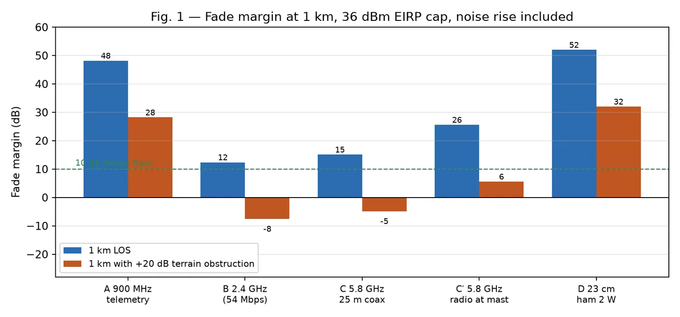
| 900 MHz margin at 1 km | 48.2 dB line of sight; +28.2 dB with a +20 dB obstruction | 1 W, 3 dBi rover, 16 dBi base, 3 dB noise rise |
| 2.4 GHz margin at 1 km | 12.4 dB line of sight; −7.6 dB with a +20 dB obstruction | 28 dBm, 5 dBi rover, 18 dBi base, 10 dB noise rise |
| 5.8 GHz margin at 1 km | 15.1 dB with 25 m of coax; 25.6 dB with the radio at the mast | 25 dBm, 13 dBi panel, 29 dBi base |
| 23 cm margin at 1 km | 52.0 dB line of sight; +32.0 dB with obstruction | Licensed amateur, 2 W, 12 dBi rover, 15 dBi base |
| 25 m LMR-400 loss | 3.2 dB at 900 MHz, 5.5 at 2.4 GHz, 10.7 at 5.8 GHz | Datasheet S-VENDOR-TIMES-LMR400 |
| 900 MHz channel plan | 32 hops at 250 kHz spacing; 16 at 500 kHz | FCC needs at least 25 hops S-FCC-15-247 |
| EIRP ceiling | 36 dBm, so a 29 dBi dish may be fed about 7 dBm | The fixed point-to-point exemption does not cover a moving rover S-FCC-15-247 |
| Measured obstruction collapse | 850 m to 300 m, and 750 m to 164 m | WVU 2023 and 2026 S-WVU-SAR2023 S-WVU-SAR2026 |
| Latency budget | 70 to 230 ms glass to glass; target ≤250 ms | Camera, encode, air, decode, command; estimated |
| Video demand | six 720p30 streams at 3 Mbit/s is 18 Mbit/s | Impossible on 900 MHz, marginal on a contested 2.4 GHz link |
Design space, in one table
| Decision | Options | Recommended for a first build |
|---|---|---|
| Band | 900 MHz · 2.4 GHz · 5.8 GHz · 23 cm · 70 cm | 2.4 GHz primary, 900 MHz recovery, 5.8 GHz as an optional third plane |
| Architecture | single band · two planes · three planes | Three independent planes, each with its own antenna and power feed |
| Base antenna | omni · 90–120° sector · 29 dBi dish | 16–18 dBi 90–120° sector: gain with the coverage a moving rover needs |
| Rover antenna | 3–5 dBi omni · 13 dBi panel | 5–10 dBi omni on a 2–3 m mast, or a 13 dBi panel if the rover can be aimed |
| Feedline | 25 m coax · radio at the mast on PoE | Radio at the mast: 10.5 dB recovered at 5.8 GHz, and one fewer connector chain |
| Video transport | MJPEG · RTSP H.264 · WebRTC · analog | Hardware H.264 at 720p with an operator-selectable 6 Mbit/s fallback |
| Rate control | fixed rate · operator-selected rate ladder | Operator-selectable: falling from MCS7 to 6 Mbit/s buys about 9× the range at 2.4 GHz |
At 1 km every option closes, and two effects still kill the link
The headline budgets are comfortable: 900 MHz closes 1 km with 48 dB of margin, 2.4 GHz with 12 dB, 5.8 GHz with 15 dB, all at compliant EIRP. A team that fails at URC did not fail a free-space calculation. Two effects outside that calculation decide the outcome.
Close-in overload. At 5 m the 900 MHz architecture with a 16 dBi yagi puts +2.6 dBm into the receiver, as does 5.8 GHz with the radio at the mast. Most radios specify a −10 dBm maximum input. Every mission begins with a close-in leg, so the design needs transmit power control or a fixed attenuator, tested at 5 m rather than at 1 km.
Terrain. With 20 dB of obstruction the two Wi-Fi bands go negative, at −7.6 dB for 2.4 GHz and −4.9 dB for 5.8 GHz on 25 m of coax, while 900 MHz stays at +28.2 dB. WVU measured the collapse in its own tests: 850 m of line of sight became 300 m obstructed in 2023, and 750 m became 164 m in 2026 S-WVU-SAR2023 S-WVU-SAR2026. The judges’ advice to design for both near and far operation is a direct statement of these two columns S-URC-ADVICE.
Height is worth more than band choice in the open
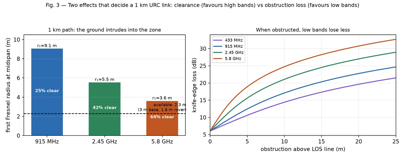
The first Fresnel radius at the middle of a 1 km path is 9.1 m at 915 MHz, 5.5 m at 2.45 GHz and 3.6 m at 5.8 GHz. With a base antenna at its 3 m limit and a rover antenna at 1.6 m, the line between them is only 2.3 m above the ground at midspan, so the 60 % clearance criterion is met at 5.8 GHz and nowhere else. That is the opposite of the obstruction result, and the two effects pull against each other: low bands need more clearance but lose less when they do not get it.
The practical consequence is that mast height is the cheapest gain on the link. Raising the rover antenna from 0.6 m to 3.0 m recovers about 14 dB at 915 MHz and 14.7 dB at 2.4 GHz on flat ground, which is the same order as switching bands. WVU grew its rover mast from 2 m in 2023 to 3 m in 2025 and reduced antenna mass to pay for it S-WVU-SAR2023 S-WVU-SAR2025. The rover mast is therefore a communications component that the structures and mobility pages also have to carry, and it is the item most likely to break the 1.2 m cube when stowed.
The 900 MHz sub-band is a rules problem before it is a radio problem
The 2027 rule is unusually specific. Occupied bandwidth is capped at 8 MHz, operation must sit exclusively inside 902–910, 911–919 or 920–928 MHz, the schedule assigns the sub-band per mission, and the restriction covers every link between the C2 station, the rover, the drone and the astronaut, including local-area networks between devices at any location, and URC monitors the spectrum on site to police it S-URC27-RULES §2.c.v.
The FCC hop-count rule then depends on the occupied bandwidth, not the channel spacing S-FCC-15-247. Below 250 kHz the requirement is at least 50 hopping frequencies, which an 8 MHz window cannot hold. Between 250 and about 320 kHz the requirement is at least 25, and 250 kHz spacing gives 32, which complies. At 500 kHz the window holds 16, which fails. A team that buys a radio on its data rate and its price has not answered this question.
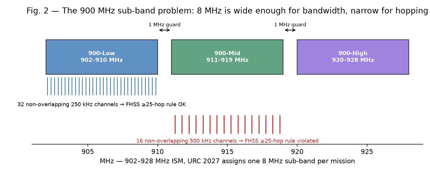
The concrete trap is in the shipped configuration. The RFD900x-US is a 1 W modem with a published 224 kbit/s ceiling, and it ships with two selectable sub-bands, 902–915 and 915–928, neither of which is one of the three 2027 windows S-VENDOR-RFDESIGN-RFD900X. The workable answer is three saved profiles with the frequency limits set to the assigned window, each verified in set-up. That is a configuration task on every run, and the failure it prevents is a rules breach rather than a performance loss.
Three planes, not one band
WVU is the closest thing to a controlled experiment in the published record: first in 2023, second in 2024 and 2025, fourth in 2026, with a communications paragraph in every System Acceptance Review.
| Year | Primary link | Recovery | Rover antenna and mast | Range tested | Source |
|---|---|---|---|---|---|
| 2023 | 900 MHz, Cambium PTP 450 | none | two 5 dBi whips on a 2 m telescoping mast | 850 m line of sight, 300 m obstructed | S-WVU-SAR2023 |
| 2024 | 2.4 GHz, 90° sector at the base | 900 MHz, 120° sector | omni | 250 m on 2.4 GHz, 1 km on 900 MHz | S-WVU-SAR2024 |
| 2025 | 2.4 GHz, 90° sector | 70 cm packet radio and 433.25 MHz analog television | collinear omni on a 3 m mast | 750 m, with a seamless transition to the recovery plane | S-WVU-SAR2025 |
| 2026 | 2.4 GHz multi-video plus 5.8 GHz | 70 cm | collapsible mast with a gimbal camera | 750 m line of sight, 164 m obstructed in noise | S-WVU-SAR2026 |
The sequence shows a team moving up in frequency for bandwidth and down in frequency for survival, and ending with three planes rather than a better band choice. The E-stop makes the pattern necessary rather than elegant: the single kill removes all battery power, so the rover radio dies with everything else, and the C2 station sees silence that is expected rather than a fault S-URC27-RULES §2.a.v. A recovery plane that carries a heartbeat and drive commands at low rate is what keeps a bad minute recoverable.
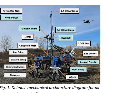
The System Acceptance Review that describes this arrangement is itself the primary source for the 2026 row of the table, and it shows the mast, the antennas and the gimbal camera in service.
Antenna gain belongs at the receiver. Teams routinely put a 1 W radio on a 20 to 29 dBi antenna. That is legal for a fixed point-to-point link in 5.8 GHz and illegal for a moving rover anywhere, because EIRP is capped at 36 dBm S-FCC-15-247. The cap costs nothing in practice: EIRP is what the far end receives, the receiving gain is unregulated, and the correct move is to back the transmitter down and take the gain at the base station. A 29 dBi dish thereby becomes a receive-gain device, which is why the lower-gain sector is the better first choice: the judges warn that the rover will not always be in front of the antenna S-URC-ADVICE.
Interfaces that bite
- Power. The kill removes battery power, so the radio dies with the rover. Link loss after a kill is expected, not a fault, and the field judge has to read the rover’s own status indicator instead. The radio also needs a quiet 12 V rail, because a radio sharing a rail with a motor controller drops packets when the drive moves S-URC27-RULES §2.a.v.
- Sensors and perception. Six 720p30 streams at 3 Mbit/s is 18 Mbit/s, which 900 MHz cannot carry and a contested 2.4 GHz link carries badly. The camera count is a link-budget decision, taken before the cameras are bought.
- Autonomy. The link-loss behaviour is a scoring feature. Autonomy allows a stop-and-return at a 20 % penalty or teleoperation back at 50 %, and Delivery does not allow either S-URC27-RULES §1.e.xviii. The state machine that holds, stops and returns has to work over the recovery plane.
- Operator station. Signal strength, noise floor and latency have to be continuously visible, with a one-action drop to 6 Mbit/s. Without that control the operator cannot trade rate for range.
- Delivery and astronaut. A drone relay is allowed and explicitly encouraged but unproven in this record, and a battery swap counts as an intervention S-URC27-QA S-URC27-QA RQ5 RQ14. A suited astronaut adds a third node on the same bands, and may carry electronics but may not deploy a repeater S-URC27-QA AUQ26.
Failure modes
The failure record is consistent, and it is dominated by physics rather than by component choice.
| Mechanism | What happens | Prevention |
|---|---|---|
| Terrain and non-line-of-sight | The link works on the flat and dies behind the hill, at 164 m instead of 750 m | A lower-band recovery plane with its own antenna; route planning that keeps the rover inside the base sector |
| Feedline loss | 25 m of LMR-400 costs 10.7 dB at 5.8 GHz, which is the whole gain advantage of a panel over an omni | Radio at the mast on PoE, or LMR-600, and count the feedline in the budget |
| Receiver overload | The close-in leg saturates the front end and the link appears to fail at short range | Transmit power control, automatic gain control, or a fixed 10–20 dB attenuator, tested at 5 m |
| Interference from the field | About 36 teams arrive with 2.4 GHz and often 900 MHz gear; the quiet parking lot is not the venue S-URC27-TEAMINFO | Sub-band agility, a channel plan written before arrival, and a scan during set-up |
| Regulatory non-compliance | Non-compliant EIRP or missing documentation fails the April deadline | One compliance line per radio: band, conducted power, antenna gain, EIRP, rule |
| Vibration and transport | Wiring and connectors work in the parking lot and fail at the site S-URC-ADVICE | Locking connectors, strain relief, a spare antenna cable, and a link test after every transport leg |
| Single plane of failure | One radio is one failure domain | Two planes on different bands, independently powered |
The gap in that record is worth stating: no public URC post-mortem reports measured link data such as throughput, signal strength or packet loss, so the record is judges’ statements plus each team’s own tested ranges. A team that instruments its link and publishes the numbers would be ahead of the field.
Shortlist for a first build
| Item | Choice | Why |
|---|---|---|
| Primary plane | 2.4 GHz, 802.11ac, radio at the mast on PoE | Cheapest established ecosystem, video-native, and 12 dB of margin at 1 km with a 10 dB interference allowance |
| Recovery plane | 900 MHz, 1 W modem, three saved sub-band profiles | +28 dB when obstructed, and the band that survives the intentional non-line-of-sight |
| Third plane | 5.8 GHz, radio at the mast, optional | Quietest unlicensed band on site, 25.6 dB of margin at 1 km with the radio at the antenna |
| Base antenna | 16–18 dBi, 90–120° sector on a 3 m mast | Gain with the coverage a moving rover needs, and no aiming problem |
| Rover antenna | 5–10 dBi omni on a 2–3 m mast | No steering hardware; mast height buys about 14 dB |
| Video | Hardware H.264 at 720p, operator-selectable 6 Mbit/s fallback | One driving stream plus on-demand detail streams fits the link |
| Documentation | One compliance line per radio, plus the licence copies | The April deadline is a documentation task, not a radio task |
Open problems
- What is the noise floor at the competition site? There is no measured spectrum data at MDRS. The 3, 6 and 10 dB interference allowances are estimates, and they are the difference between a 12 dB and a 22 dB margin at 1 km. A 60-second scan at a comparable multi-team event settles it.
- What does the 2027 terrain profile actually look like? Base siting and the value of a relay depend on geometry that is not published. A digital elevation model of the area plus the candidate base positions gives Fresnel clearance to the far corners.
- Does the candidate radio shift sub-bands on command? The vendor documents two windows, the rules require three. A bench check with a spectrum display, counting hops inside 8 MHz, is the test.
- What is the receiver’s maximum input? Most radios do not publish a compression point, and the close-in case exceeds the typical limit. A bench test that feeds a known level into each radio finds it.
- What is the real glass-to-glass latency? The 250 ms target is an engineering estimate. A camera pointed at a millisecond clock measures it at 1 km, at 100 m and at three video rates.
- Does a relay earn its place? Two hops turn a failing obstructed link into two comfortable ones, but no team in this record documents a deployment. A two-hop test with a mast at 100 m measures throughput and latency on both legs.
Further reading
- WVU carries four years of published communications detail and the only measured obstruction numbers in the record. Waterloo published its own radio research and is the clearest example of a team documenting the trade rather than the outcome.
- Power, electrical architecture and safety owns the other half of the E-stop problem: the kill that removes battery power also removes the radio.
- Compute, sensors and perception sets the camera count that the link has to carry.
- Interfaces and couplings traces the communications, power and autonomy couplings with numbers.
- The Q&A rulings carries the answers on relays, sub-bands and the base station.
Sources for this page
- S-URC27-RULESUniversity Rover Challenge 2027 – Requirements and GuidelinesOriginal Archived copy
- S-URC27-QAURC2027 Questions & Answers (updated through 2026-10-11)Original Archived copy
- S-VENDOR-TIMES-LMR400Times Microwave LMR-400 datasheet (hosted by Talley): attenuation 12.8 dB/100 m @900 MHz, 22.2 @2500 MHz, 42.7 @5800 MHzOriginal
- S-FCC-15-24747 CFR §15.247, Operation within the bands 902–928 MHz, 2400–2483.5 MHz, and 5725–5850 MHz (FHSS channel counts, 1 W conducted, 6 dBi antenna rule, 36 dBm EIRP, fixed-PtP exemption)Original
- S-WVU-SAR2023Team Mountaineers System Acceptance Review 2023 (rover "Wanderer"): Cambium PTP 450 900 MHz link, 850 m LOS / 300 m NLOS, 2 m telescoping mast, drone 900 MHz + 2.4 GHzOriginal
- S-WVU-SAR2026Team Mountaineers System Acceptance Review 2026 (rover "Deimos"): tri-modal 2.4 GHz + 5.8 GHz + 70 cm, gimbal camera on antenna mast, 750 m LOS / 164 m NLOS high-noise test, antenna + radio budget linesOriginal
- S-URC-ADVICEURC Advice (judges' systems-engineering lessons)Original Archived copy
- S-WVU-SAR2025Team Mountaineers System Acceptance Review 2025 (rover "Daedalus"): 2.4 GHz 90° sector + 3 m rover mast, 70 cm HAM packet radios, 433.25 MHz amateur-TV analog video, 750 m LOSOriginal
- S-VENDOR-RFDESIGN-RFD900XRFDesign RFD900x-US modem page: 1 W (30 dBm), 902–928 MHz, 12–224 kbps, sensitivity −111/−105/−98 dBm, 18 g, FCC ID 2ADLE-900X, AUD 177.80 excl. GST; lists only two selectable sub-bands (902–915, 915–928)Original
- S-WVU-SAR2024Team Mountaineers System Acceptance Review 2024 (rover "Heimdall"): dual-band 2.4 GHz + 900 MHz, 90°/120° sector antennas, 250 m / 1 km tested, antenna and radio budget linesOriginal
- S-URC27-TEAMINFOURC2027 Team Info / registration pageOriginal Archived copy